Guangzhou Lvyuan Water Purification Equipment Co., Ltd. is an industrial filter manufacturer founded in 2009 that designs and manufactures stainless steel filter housings, stainless steel sterile water tanks, filter elements, filter bags, ultra-polymer materials, and sintered filter products. Buyers choose Lvyuan for OEM/ODM support, ISO9001 quality control, and multi-country certifications.
Guangzhou Lvyuan Water Purification Equipment Co., Ltd.
Filter Housing Safety Factors for 10-15 Bar Applications
A filter housing rated “10 bar” or “16 bar” on a quotation tells a buyer very little about how much margin the vessel actually has. At 10–15 bar, the housing shell is often not the weakest part. The closure, gasket, connection, gauge or an unplanned pressure surge can set the real limit. “Safety factor” also means different things in different documents: a material design margin, the gap between operating and design pressure, or the multiplier used in the factory pressure test.
This guide separates those meanings and shows where margin is lost in a stainless steel filter housing. It covers how test pressures are calculated, when pressure-equipment regulations apply, and what to put in an RFQ, so procurement and engineering teams can compare housings like for like.
What Does “Safety Factor” Mean for a Filter Housing?
There is no single safety factor for a filter housing. Buyers meet at least four different margins, and a brochure that quotes only one of them can hide the others.
Term
What it describes
Who sets it
What to ask the supplier
Operating pressure
Normal working pressure in the line
Process or system designer
Normal and maximum values, including pump shut-off pressure
Design pressure (PS or MAWP)
Pressure the housing is calculated and certified for, at a stated temperature
Housing manufacturer, under a design code
Which code, which temperature, which corrosion allowance
Set pressure of the relief device
Pressure at which protection opens
System designer
Whether the housing’s design pressure sits above this value
Test pressure
Pressure applied to each finished housing to prove strength and tightness
Design code or buyer specification
Test factor, hold time, test medium, report format
Burst pressure
Pressure at which a sample fails
Type testing, usually destructive
Whether burst data comes from a real test or an estimate
The material design margin, meaning how far the code’s allowable stress sits below the metal’s tensile or yield strength, sits behind the design pressure and varies by code. According to one ASME Section VIII Division 1 hydrotest guide from EPCLand, post-1999 ASME vessels use a design margin of 3.5 on tensile strength, down from 4.0 earlier. A “4:1 safety factor” on a datasheet therefore cannot be compared directly across design codes. Ask which code the number belongs to.
Why a Higher Pressure Rating Is Not the Same as More Margin
A common assumption is that a 16 bar housing is automatically safer than a 10 bar housing in the same service. That holds only if the rated pressure is governed by the same component in both designs, and if the gap between maximum credible pressure and design pressure is what you think it is.
Consider an illustrative system, not a real project. Normal operating pressure is 7 bar. The pump’s shut-off pressure is 12 bar, and the relief valve opens at 13 bar. A housing with a 10 bar design pressure has no margin at all in this system, even though 7 bar looks comfortable. A housing designed for 15 or 16 bar has a real margin. The deciding number is the maximum credible pressure, not the normal one.
The reverse also applies. Specifying 16 bar for a gravity-fed or low-pressure line adds shell thickness, flange weight and cost without improving safety in any way the process can use. Match design pressure to the highest pressure the system can produce, then confirm that every component is rated for it. Reading a filter housing pressure rating without that context invites the wrong purchase in either direction.
For reference, where Lvyuan’s linked product pages state a pressure rating, it is 10 bar or lower. The sanitary multi-cartridge housing is listed at a maximum of 145 psi (10 bar) and 150°C, and the mobile filtration cart discussed below is listed at 6 bar. None of the linked product pages states a 15 bar rating. For duty above a listed rating, request a project-specific design confirmation instead of assuming the standard model can be stretched.
Where the Real Margin Sits: Component-by-Component Checks
A housing is a pressure boundary made of several parts. Its safe working pressure is set by the weakest of them at the design temperature.
Shell, Heads and Welds
Wall thickness, head shape and weld quality set the capacity of the body. Polished or electropolished surfaces improve cleanability but add nothing to pressure strength. A thin-wall polished sanitary body can be well suited to hygienic service and still need a pressure calculation, not an assumption from its appearance. Ask for the design calculation or a code-based design report, plus weld inspection records.
Closures: Where Pressure Load Concentrates
Closure load grows with the square of the sealed diameter. At 15 bar (1.5 MPa), a 300 mm sealing diameter carries roughly 106 kN of separating force. At 10 bar, a 100 mm diameter carries about 7.9 kN. Larger housings at higher pressure therefore need deliberate closure design, not just a thicker wall.
Closure types behave differently:
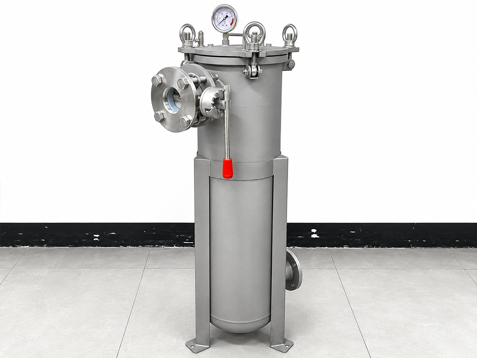
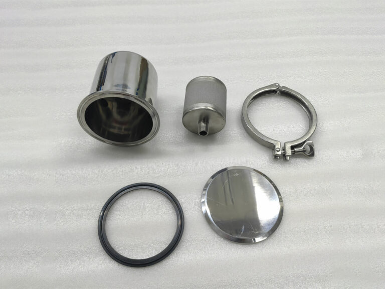
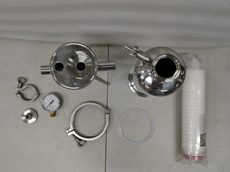
Clamp-band closures suit sanitary designs, such as the stainless steel sanitary cartridge filter housing with clamp connections and a quick-opening closure. Verify the clamp’s rating, the sealing surfaces and the gasket material for the pressure and temperature in question.
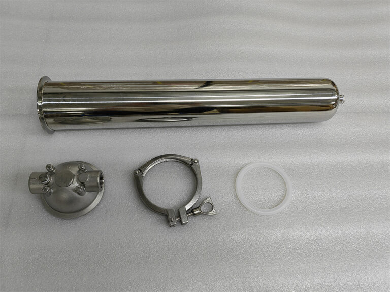
Quick-release clamps with threaded ports are common on compact units like the single cartridge filter housing with threaded connections. Threaded ports in a stainless body need confirmed pressure ratings and a sealing method suited to the fluid.
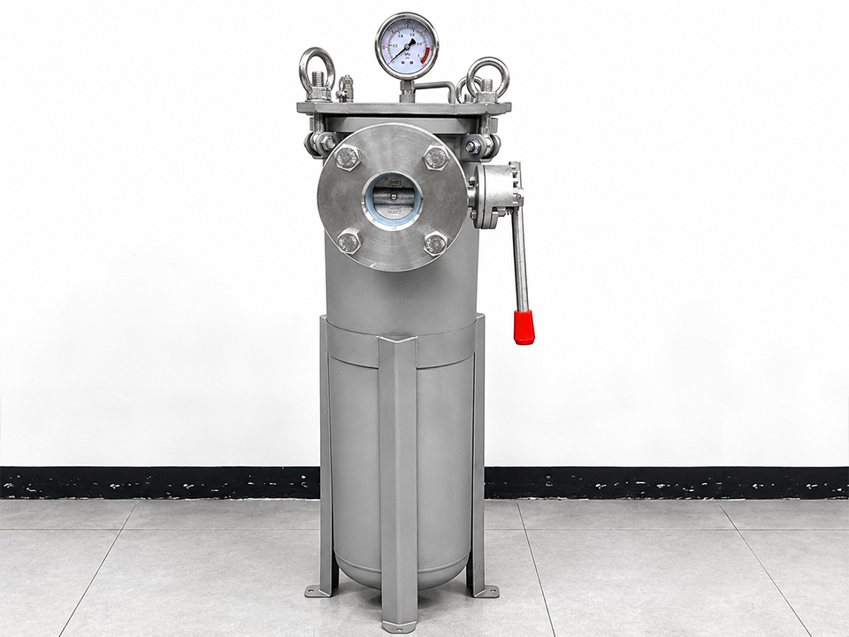
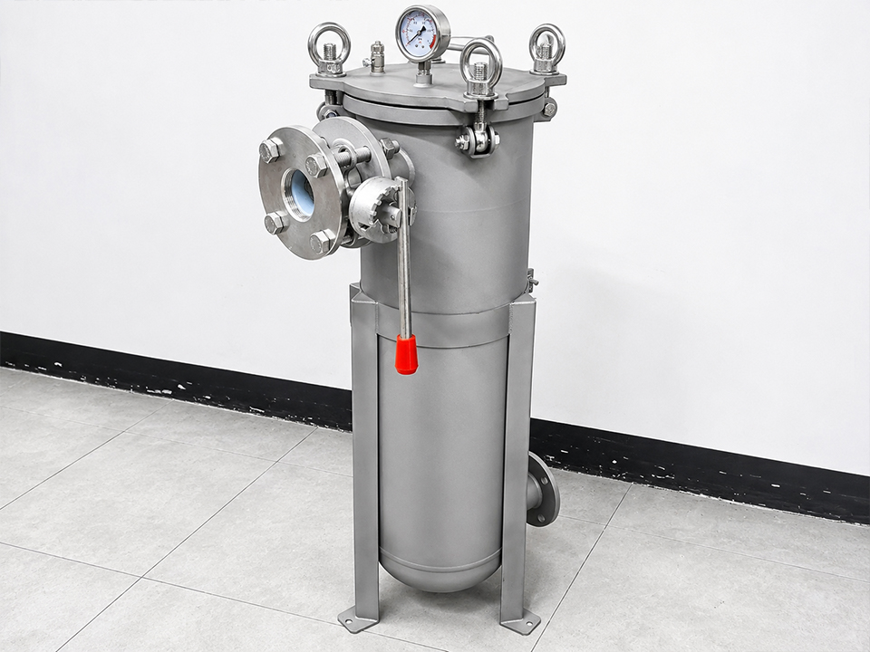
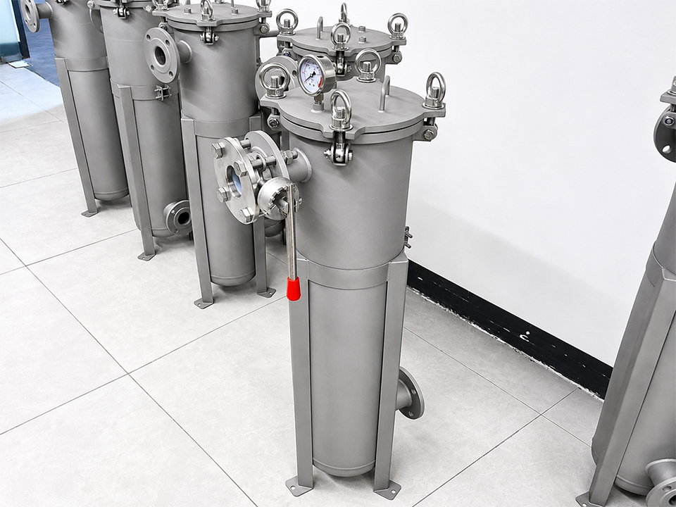
Bolted flange covers such as the one on the flanged sintered cartridge filter housing spread load across multiple bolts and suit gas, steam and liquid duties, but bolt torque and gasket selection then determine tightness.
Swing eye-bolt covers allow fast access, as on the side-entry stainless steel bag filter housing. Check the bolt material and count against the cover diameter, and confirm the cover seal for repeated opening.
Connections and Flange Class
Flanges are a frequent limiting component. According to Forgepoint Engineering’s explanation of ASME B16.5 flange classes, a class number such as 150 is a designation, not a pressure rating. The allowable pressure depends on the material group, temperature and the applicable code. Low-carbon “L” grades also carry lower ratings than standard 304 or 316. In an ASME B16.5 pressure-temperature table reproduced by Unified Alloys, Class 150 at ambient temperature is 275 psi (about 19 bar) for Type 304 and 316 but 230 psi (about 15.9 bar) for 304L and 316L. That is only just above a 15 bar design pressure before temperature derating, and many sanitary housings are built in 316L. At 10–15 bar, a Class 150 or PN16 flange can leave little room once temperature rises. Verify the figures against the current standard, and request the pressure-temperature rating of the actual flange material at your design temperature.
Sanitary tri-clamp joints need the same scrutiny. Rated pressure depends on the ferrule size, the clamp type and the gasket, and it generally falls as diameter increases. Ask for the rating of the full joint, not of the housing body alone.
Gauges, Vents and Drains
These small ports are part of the pressure boundary. Gauge range matters too. According to Tameson’s summary of EN 837-2 gauge selection, the maximum working pressure should not exceed 75% of full scale for steady pressure, or 65% for cyclic pressure. A 0–10 bar gauge on a 10 bar housing would break that guidance. A 0–16 bar gauge is the more sensible pairing for 10 bar service.
Internal Elements
The housing rating does not describe the filter element. Cartridges, bags and baskets each have a separate differential pressure limit, and a blocked element raises pressure drop while upstream pressure remains the same. Housing and element ratings are independent, so confirm both.
How Are Test Pressures Calculated?
Test pressure is a multiple of design pressure, set by the design code. Two reference points are widely used.
PED (Directive 2014/68/EU): Annex I specifies a hydrostatic test pressure equal to the greater of two values. The first is 1.25 times the maximum loading in service, taking account of maximum allowable pressure and temperature. The second is the maximum allowable pressure multiplied by 1.43, as set out in the Pressure Equipment Directive text on EUR-Lex.
ASME Section VIII Division 1: The standard hydrotest under UG-99 is at least 1.3 times MAWP, corrected for the lowest stress ratio between test and design temperature, according to the EPCLand guide cited above. The guide is a secondary source, so confirm the clause against the current code edition.
The table below shows the arithmetic floors for typical design pressures. These are calculated minimums, not supplier data, and the PED figure can be higher at elevated design temperatures.
Design pressure
PED floor (1.43 × PS)
ASME floor (1.3 × MAWP, before stress ratio)
10 bar
14.3 bar
13.0 bar
12 bar
17.2 bar
15.6 bar
15 bar
21.5 bar
19.5 bar
16 bar
22.9 bar
20.8 bar
Two practical consequences follow. First, the test pressure of a 15 bar housing is above the nominal rating of many common line components, so the housing must be tested isolated, with the element removed and openings blanked. Second, some supplier literature quotes test factors that do not match these code values, so ask which code the factor comes from. A hydrostatic test should be water-based, drained, and dried afterwards. For stainless steel, the EPCLand guide also advises checking chloride levels in the test water and drying the vessel promptly.
Does a Small Liquid Housing Need PED CE Marking?
Often not, but the answer depends on fluid, volume and temperature. Article 4 of Directive 2014/68/EU sets the thresholds, and equipment below them falls under “sound engineering practice” and must not carry the PED CE mark.
For vessels holding liquids with low vapour pressure in Group 2 (broadly, fluids not classed as hazardous), full PED requirements apply only when PS exceeds 10 bar and the product of PS and volume exceeds 10,000 bar·L. A 15 bar water housing would need a volume above roughly 667 L to reach that threshold. Cartridge and bag housings are far smaller.
The limits are much lower in other cases:
Gases and vapours in Group 2: PS × V above 50 bar·L, which at 15 bar is about 3.3 L.
Group 1 (hazardous) liquids: PS × V above 200 bar·L.
Liquids whose vapour pressure at maximum temperature exceeds 0.5 bar above atmospheric are treated like gases, which can include hot water above roughly 110°C.
So a housing for steam, compressed gas or hot process liquid may need full conformity assessment, while a cold-water housing of the same size may not. “Sound engineering practice” is not a loophole. It means the housing still needs a documented design basis, a pressure test and instructions for use. Treat a missing CE mark on a small liquid housing as normal, and a missing design calculation and test report as a problem.
Surge, Pulsation and Temperature Effects
Three conditions erode margin without showing up in the steady-state numbers.
Pressure surge. Rapid valve closure or pump trip creates a pressure wave. The Joukowsky relationship estimates surge as fluid density × wave speed × velocity change. In water-filled steel pipe, wave speeds on the order of 1,000 m/s are typical, so a sudden 1 m/s velocity change can imply a pressure rise on the order of 10 bar. This is an illustrative estimate; real surges depend on closure time, pipe stiffness and line length. Where quick-closing valves or pump starts are present, specify the surge or the surge-control measures.
Pump-driven systems. Skid and cart designs combine housings with pumps, valves and instruments, so the lowest-rated component sets the system limit. The mobile stainless steel filtration cart is listed at 87 psi (6 bar) and 80°C maximum, so a cart’s rating can sit below that of the individual housings fitted to it. Ask for a system-level rating.
Debris and fouling. Upstream strainers protect the housing, pump and seals from particles. A stainless steel basket strainer listed at 150 psi (10 bar), or an industrial basket strainer with quick access cover listed up to 10 bar, covers coarse prefiltration, but it adds another pressure-boundary component that needs its own rating at design temperature.
Temperature and cycling. Allowable stress and flange ratings fall as temperature rises, and elastomer seals soften or swell. Sanitary lines with hot cleaning or sterilisation cycles add thermal cycling and, with pulsation, fatigue loading. State the full temperature range and expected cycle pattern in the RFQ.
Trade-Offs: What Extra Margin Costs
Higher design pressure raises cost through thicker material, heavier flanges, larger closure hardware, a higher test pressure and, depending on the code, more inspection. It also adds weight to the housing and its supports. Pay for margin against specific risks, such as pump shut-off, surge or hot-service derating, instead of adding a blanket pressure class.
Option
Advantage
Limitation
Best fit
Design pressure matched to maximum credible pressure plus defined margin
Lowest cost for a justified margin
Requires accurate system data
Well-characterised systems with relief protection
Next standard pressure class (for example 16 bar)
Simple to specify; standard flange classes
Heavier and costlier; may not fix the weakest component
Variable or poorly known pressure profiles
Custom design above standard range
Fits unusual duty
Longer lead time; needs design verification and test
Pressure above standard product ratings
What Documents Should a Buyer Request?
For 10–15 bar housings, ask for these items before ordering:
Design code and design calculation summary, including design pressure and temperature.
Material test certificates for pressure-retaining parts and welding records.
Hydrostatic test report with the test pressure, hold time, medium and calibrated gauge details.
Pressure-temperature ratings for flanges, clamps, ports and seals.
Seal and gasket material and its compatibility with your fluid and cleaning chemicals.
Evidence of burst or type testing, if the supplier claims a burst rating.
What Should Buyers Specify Before Requesting a Quote?
An accurate RFQ lets a supplier size the design and quote a realistic test plan. Include:
Fluid and group: Name, concentration, and whether it is hazardous, a gas, steam, or a liquid near its boiling point.
Pressures: Normal operating, maximum operating, pump shut-off, relief set pressure and any known surge.
Temperature: Minimum and maximum, plus any CIP or SIP cycles.
Design code and market: The code you require (such as ASME, PED-aligned design, or another national code) and the destination country.
Test requirements: Test factor, hold time, whether you want to witness the test, and the report format.
Connections: Flange standard and class, tri-clamp size, or thread type.
Cartridge or bag format: Element type, length, micron rating and the differential pressure limit.
Cycle life: How often the housing is opened, and whether pressure is steady or pulsating.
Documentation: Material certificates, weld records, surface finish report.
If a quote lists only “10 bar” or “16 bar”, ask which component governs and at what temperature the figure applies.
Frequently Asked Questions
What safety factor should a filter housing have at 10–15 bar?
No single number applies. Codes build in a material design margin, then add a hydrostatic test, typically 1.3 to 1.43 times design pressure. Buyers should set design pressure above the maximum credible system pressure, including pump shut-off and relief setting, and require a code-based test.
Do I need a 16 bar housing for 10 bar operating pressure?
Not automatically. If the pump shut-off, relief setting or surge can exceed 10 bar, a 16 bar design is justified. If the maximum credible pressure is 10 bar or lower, a properly rated 10 bar housing may be enough. Check weakest components, not only the shell.
What hydrostatic test pressure applies to a 15 bar housing?
Under PED, the test pressure is at least 1.43 times PS, or 21.5 bar at 15 bar. Under ASME VIII-1, the standard test is at least 1.3 times MAWP, or 19.5 bar before the stress-ratio correction. Always confirm the governing code.
Does a 10 bar stainless steel filter housing need PED CE marking?
Often not for small liquid housings, because Group 2 liquid vessels only fall into PED categories above 10 bar and 10,000 bar·L. Gas, steam, hazardous fluids and hot liquids have much lower thresholds. Confirm fluid group and volume with the supplier.
Is burst test data required for a filter housing?
Not for routine production. A burst test is destructive and is normally a type or prototype test. Every production housing should instead pass a non-destructive hydrostatic test. Ask whether any stated burst figure comes from a real test report or a calculation.
Does temperature reduce a filter housing’s pressure rating?
Yes. Allowable stress in the metal, flange pressure-temperature ratings and seal capability all decrease as temperature rises. A figure such as “10 bar” is only meaningful with a stated temperature, so always specify design temperature in the RFQ.